


Altium Designer 18 có nhiều thay đổi về giao diện, kỹ sư thiết kế cần làm quen với panel thuộc tính mới. Trong bài viết này mình xin hướng dẫn cách thao tác để thêm các đối tượng 3D model vào PCB, thư viện linh kiện.
Chuyên sang chế độ view 3D: View » 3D Layout Mode hoặc ấn phím tắt số 3 bên bàn phím chữ.
Định dạng 3D mà altium hỗ trợ:
- STEP –
*.Stpand*.Step - SolidWorks parts –
*.SldPrt - Parasolid Models –
*.x_tand*.x_b
Thao tác:
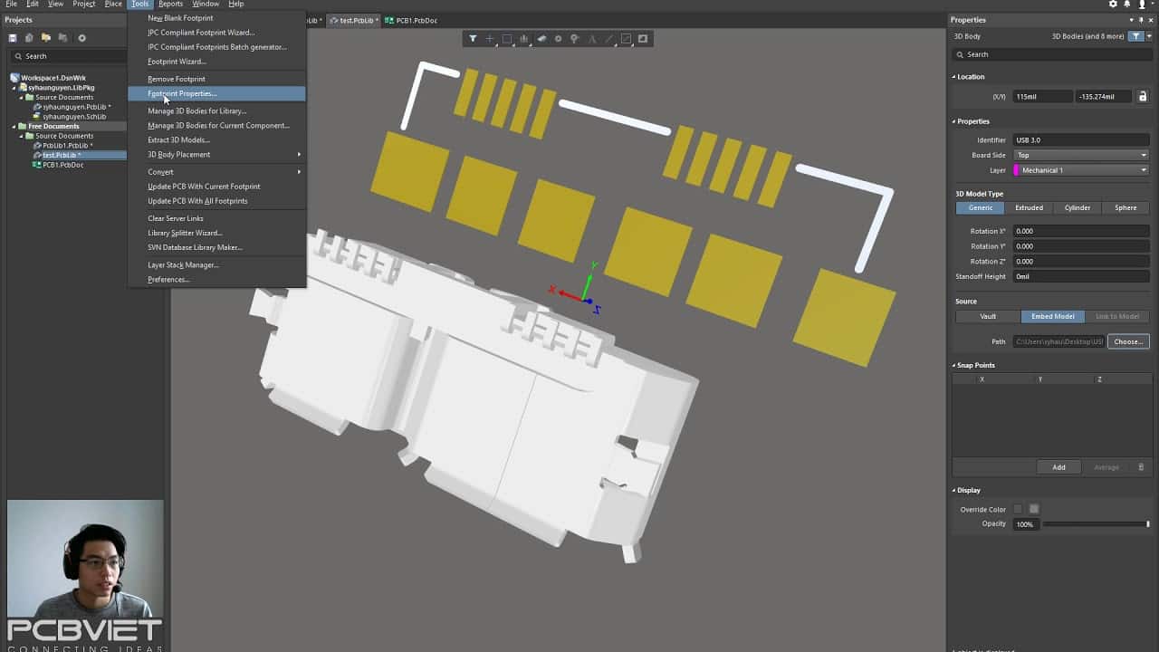
- Launch the Place » 3D Body command. The cursor will change to a crosshair and you will be in the default placement mode, placing an Extruded 3D Body object.
- Press Tab to pause placement and display the Properties panel in 3D Body mode. The workspace pause button overlay () will appear in the workspace, indicating that you can access the fields of the Properties panel.
- In the Properties panel, enter a name for the 3D Body in the Identifier field. This is optional; the Identifier can help when there are multiple 3D Bodies being placed and also can be used to target this 3D Body in a design rule, if required.
- Select the required Board Side; typically this is set to
Top. In the PCB library editor the footprint is built for the top side of the board; it can be flipped to the bottom during the PCB design process, if required. - Select the mechanical Layer on which the 3D Body is to be placed. Component-type mechanical layers should be paired with a second mechanical layer so that if the component is flipped from the top side of the board to the bottom side, its mechanical detail, such as the 3D Body, will move to the paired mechanical layer. Mechanical layers are paired in the Layers and Colors tab of the View Configuration panel. Refer to the panel page for more information.
- Select the 3D Model Type from the available shapes: Extruded, Cylinder or Sphere. Alternatively, enable the Generic option if you want to embed an external 3D model. Click here to read more on this below.
- Each shape must have a defined size before it can be placed. If the chosen shape is:
- Extruded – then define the Overall Height.
- Cylinder – define the Height and Radius.
- Sphere – define the Radius.
- In the Display region of the panel, click the Color button to set the color and adjust the Opacity as required.
- Once editing is complete, click the workspace pause button overlay to return to the workspace.
- If the shape is a Cylinder or Sphere:
- The cursor will be moving in the workspace with a rectangular shape attached; click to place the 3D Body.
- Right-click or press Esc to terminate 3D Body object placement.
- If the shape is Extruded, the cursor will present, ready to define the polygonal base shape of the extruded 3D Body:
- Click to define the first vertex.
- Move the cursor ready to place the second vertex. The default behavior is to place two edges with each click, with a user-defined corner shape between them. Refer to the Placement Modes section to learn more.
- Continue to move the mouse and click to place further vertices.
- After placing the final vertex, right-click or press Esc to close and complete placement of the 3D Body. There is no need to manually close the 3D Body as the software will automatically complete the shape by connecting the start point to the final point placed.
Xem thêm hướng dẫn chính thức của Altium Designer 18: https://www.altium.com/documentation/altium-designer/pcb-obj-3dbody3d-body-ad?version=18.1
Xem thêm những bài viết về Altium Designer tại PCBVIET: https://pcbviet.com/category/altium-designer/
